|
|||||||||||||||||||||||||||||||||||||||||||||||||||||||||||||||||||||||||||||||||||||||||||||||||||||||||||||||||||
Used Machinery Used
Air Compressors Used
Sheet Metal Brakes Used
Duct Beading Machine Used
HVAC Duct Insulation Pin Spotters Used
Pipe Equipment Used
Sheet Metal Rolls
|
Roper Whitney Folders | AutoBrake | Sheet Metal Machinery
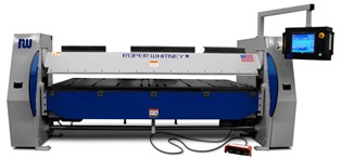
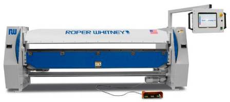
Roper Whitney Kombi Autobrake
For over 40 years, Roper Whitney has been producing quality folding systems for a variety of markets. Building on that experience, the newest generation Autobrake folders integrate advanced wing bending design with the features that have made the Autobrake the choice of professionals.. The Autobrake combines automated bending of angles up to 145°,
material clamping, and material support into a single CNC controlled
system employing wing bending techniques. Autobrake system vs. manual or press brake bending are:
INTEGRATED SHEET SUPPORT AND MATERIAL POSITIONING: Work pieces are fully supported by the table beneath the clamping jaw, and automatically positioned to an accuracy of +/- .004" by the computer controlled automatic gauge. Sheets up to 700lb. (318kg) can be accommodated. Maximum 61" (1550mm) back gauge travel in less than 3 seconds is provided by our three stage design combining high speed with compact space requirements. Operation of the pop-up fingers is controlled by the integrated air system. Air supplied to the back gauge fingers must be clean and filtered with an operating pressure of 80-100 psi. The gauging system is constructed of heavy duty yokes riding on dual linear ways. The back gauge is driven by a servo motor for low noise operation and precision ball screw for high levels of accuracy. The servo motor automatically recovers from back gauge displacements as high as .625 inches. The 14 conveniently spaced fingers provide positive contact with the sheet edge at all times and have a minimum back gauge position of 0”. "TITAN" CNC CONTROL SYSTEM: Powered by U.L. Labeled (Underwriters Laboratories) electrics,
the Titan control system combines the capabilities of Roper
Whitney's pendant control systems with new features for a quantum
leap in productivity and power. The Titan system
enhances the skills of the sheet metal fabricator by providing
the means to quickly transfer the operator's knowledge into
useful part programs. Windows-based software is combined with
a powerful machine controller, specifically designed for the
Autobrake. This system delivers a high powered stable solution
for all folding needs. The Titan software comes
packaged within an Intel® Pentium® computer combined
with a 15” flat panel display for high speed system response,
and easy viewing of the operator interface. The computer system
is pre-configured for connection to an inter-office network.
The computer is housed within a sealed oil-tight enclosure to
prevent dust and water contamination. The front of the enclosure
hinges open with the computer attached, giving access to the
USB, serial, and network connections. • 15" high resolution anti-glare flat panel touch
screen
The Titan system provides greater flexibility to the operator with fewer keystrokes, resulting in a user interface that is easy to learn, and increases productivity. Creation of part programs can be done by text entry in the main operations screen, or part profiles can be drawn and converted into programs. Both part programs and drawings can be stored on the computer's hard drive for future use. Part profile drawings are created in vector format, allowing the part to change its shape and size dynamically as bend angles and line lengths are altered. Parts can then be visually verified as correct prior to creating the part program. Bends can be inserted, deleted, or altered as the operator desires. Therefore, stored profiles can be changed into other types of shapes on demand. Hem and radius macros can also be used to create architectural shapes, or other curved forms. Part programs and drawings are stored and accessed from the
memory using a flexible Windows based file handling system.
Programs can be stored in any number of directories for easy
organization according to any factors desired, such as: customer
name, product name, part type, etc. Program file names can be
any combination of letters or numbers, allowing programs to
be identified by part form, company part number, or any other
criteria desired. Programs created using the drawing portion
of the Titan system show a small picture of the part for quick
program identification. Incorporated into the file system is
a quick search tool that allows programs to be displayed by
key portions of their names. This limits the selections displayed,
and speeds program access for the operator. The control system includes several backup features. The setup parameters that control the operation of the Autobrake can be stored at any time to a file name. These settings can then be retrieved as needed to maintain correct machine performance. This provides a fast secure method to reestablish the parameter settings due to any disruption. Once per month the operator is reminded to make a complete backup of the Titan software system. This backup stores all of the critical system settings, part programs, and part profile drawings present in the Titan operation directory. Each backup made is stored separate from the next, providing a history that can be accessed if needed, and preserving the operator's part programs. Backups are placed in a USB flash drive connected to the computer control head, or may be directed to another drive; either local or network. Programming Functions are: • Bend angle CONSTRUCTION: The Autobrake is a plate and weldment steel construction, delivering superior performance and features in a simplified rigid design. End housings are a plate-type construction bringing drive components close together for improved stiffness and performance. Actuating mechanisms are secured in rigid mounts at the outside of the housings, allowing easy maintenance. The unique Kombi beam is a fabricated structural prism on which is mounted tooling to firmly clamp a broad range of materials and withstand the forces generated by capacity forming operations. Machined into the Kombi beam 180° from each other are the attachment surfaces for the straight and box and pan tooling. Tools are attached to the Kombi beam with standard socket head cap screws and grooves are provided to secure the tools even while the clamping bars are loosened for adjustment. Rotation of the Kombi beam is powered by a brake motor driving a sprocket and roller chain mechanism. The upper beam is driven to programmed settings on both ends
by a brake motor and eccentric drive of the beam with a connecting
shaft. Clamping and hemming power is delivered to the clamp
jaws by a series of spring washers to provide variable clamping
pressures with a shock-absorbing end stop. This provides reliable
clamping pressure regardless of material thickness. Integral
to the upper beam are the ways with non-metallic gibing to guide
and retain the upper beam within the end housings. The lower beam is a welded reinforced structure fabricated of thick steel keyed into the end housings. The lower beam is pinned in place, and close-coupled to the end housings and upper beam for improved rigidity. The advanced design of this beam delivers superior hemming results. The folding beam consists of a thick plate for maximum resistance
to bending forces with a machined seat to receive the standard
.787" (20mm), .390" (10mm) or .275" (7mm) bending
blades. A micrometer nut allows adjustment for large variations
in material thickness. Access to the Autobrakes’ electrical system is located
at the right-hand portion of the machine through a quick- lock
enclosure. This enclosure houses the power and control devices
that drive the machine, and extends behind the right-hand cover
for reduced machine length. "VSD" BENDING SYSTEM: A standard feature of the Autobrake, the Variable Speed Drive system delivers advanced positioning of the bending beam in radius forming applications. This system provides precise control over the small angles used to produce these radius forms. Standard bends are also enhanced, yielding bending accuracies of + 1/2 degree. The system includes a variable speed drive, DB resistor assembly, installation, and testing. The CNC control system on the Autobrake is equipped to control and monitor the VSD system, and allows adjustment of the reduced speed settings to accommodate the customer's application.
Folding beam crowning is standard equipment on the Autobrake. This system consists of crowning cams, actuating tool, and interfacing features on the machine's bending beam. The system provides a quick easy method for adjusting the center
crown of the bending tooling to improve bend accuracy, and adjust
the work material straightness when forming radius bends. The
system is manually adjusted, and locked in place by the operator. Roper Whitney Autobrake |
||||||||||||||||||||||||||||||||||||||||||||||||||||||||||||||||||||||||||||||||||||||||||||||||||||||||||||||||||

| AB1016 | AB1014 | AB1216 | AB1214 | |
| Bending Capacity (Mild Steel) | 16ga | 14ga | 16ga | 14ga |
| Bending Capacity (Stainless) | 20ga | 16ga | 20ga | 16ga |
| Bending Length | 122" | 122" | 147.5" | 147.5" |
| Bending Bars | 0.787", 0.390", 0.250" | 0.787", 0.390", 0.250" | 0.787", 0.390", 0.250" | 0.787", 0.390", 0.250" |
| Back Gauge Depth (Standard) | 39.37" | 39.37" | 39.37" | 39.37" |
| Back Gauge Depth Increased (Optional) | On Request | On Request | On Request | On Request |
| Clamping Beam Opening Height | 4.5" | 7.3" | 7.3" | 7.3" |
| Clamping Beam Straight Bar Tooling | 30º | 30º | 30º | 30º |
| Folding Beam Adjustment | 2" | 2" | 2" | 2" |
| Crowning of the Folding Beam | 5-Point 0"-0.030" Adjustment | 5-Point 0"-0.030" Adjustment | 5-Point 0"-0.030" Adjustment | 5-Point 0"-0.030" Adjustment |
| Working Height | 35" | 35" | 35" | 35" |
| Machine Length | 155" | 159" | 181" | 181" |
| Machine Width | 56" | 89" | 89" | 89" |
| Machine Height | 60" | 68" | 68" | 68" |
| Machine Weight | 6202lbs | 8542lbs | 9842lbs | 10350lbs |
| Shipping Weight | 6912lbs | 9022lbs | 10500lbs | 11000lbs |
| Back Gauge Servo Motor | 3/4 hp | 3/4 hp | 3/4 hp | 3/4 hp |
| Clamping Beam Motor | 1.5 hp | 2 hp | 2 hp | 2 hp |
| Bending Beam Motor | 1.5 hp | 2 hp | 2 hp | 3 hp |
Return to the New Machinery Page
Return to the Home
Page
 Contact Us | Site
Map | ©2004 Cincinnati Precision Machinery, Inc. All rights
reserved.
Contact Us | Site
Map | ©2004 Cincinnati Precision Machinery, Inc. All rights
reserved.